Overview
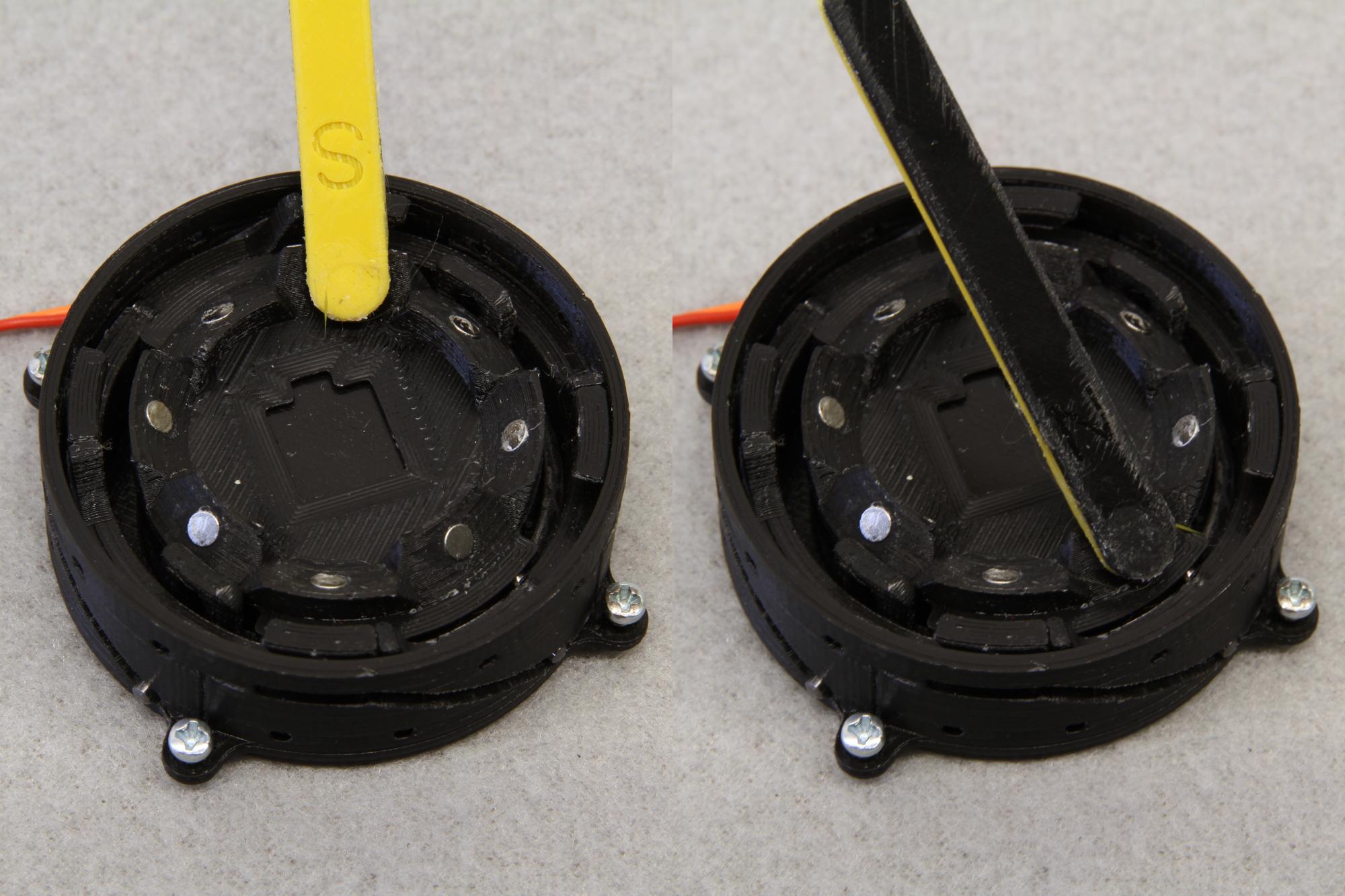
RoFI Connection Mechanism, RoFICoM for short, is an open-hardware genderless 90-degree symmetric connection mechanism for modular robots. It can establish a firm mechanical, data and power connection between two modules without any a priori synchronization. The connector is suitable for densely occupied grid-based systems as it expands when connected and retracts when disconnect. Therefore, the connector does not block adjacent modules movement. The novelty of our connection mechanism lies in new unique flat design, encapsulation and design that is optimized for hobbie desktop 3D printing. Due to the flat design there is enough space left out for internals of individual robotic modules.
See the connector in action:
Features
- compact, flat layout (diameter 50 mm, thickness 17 mm)
- data and power sharing between connected units
- load capacity
- normal direction: 110 N
- shear direction: 50 N
- actuation time: less than 0.6 s
- genderless, 90-degree symmetrical with automatic orientation detection
Interface
The connector is a stand-alone unit with well defined interface and therefore, it can be treated as a black box. The connector exposes SPI slave interface for the module and via this interface, allows the module to control the connector and also send arbitrary binary blobs to the connected connector.
Mechanical Dimensions
The connector provides 4 M2 mounting holes around its perimeter, the red arrow denotes the orientation vector of the connector:

Connector to Connector Interface
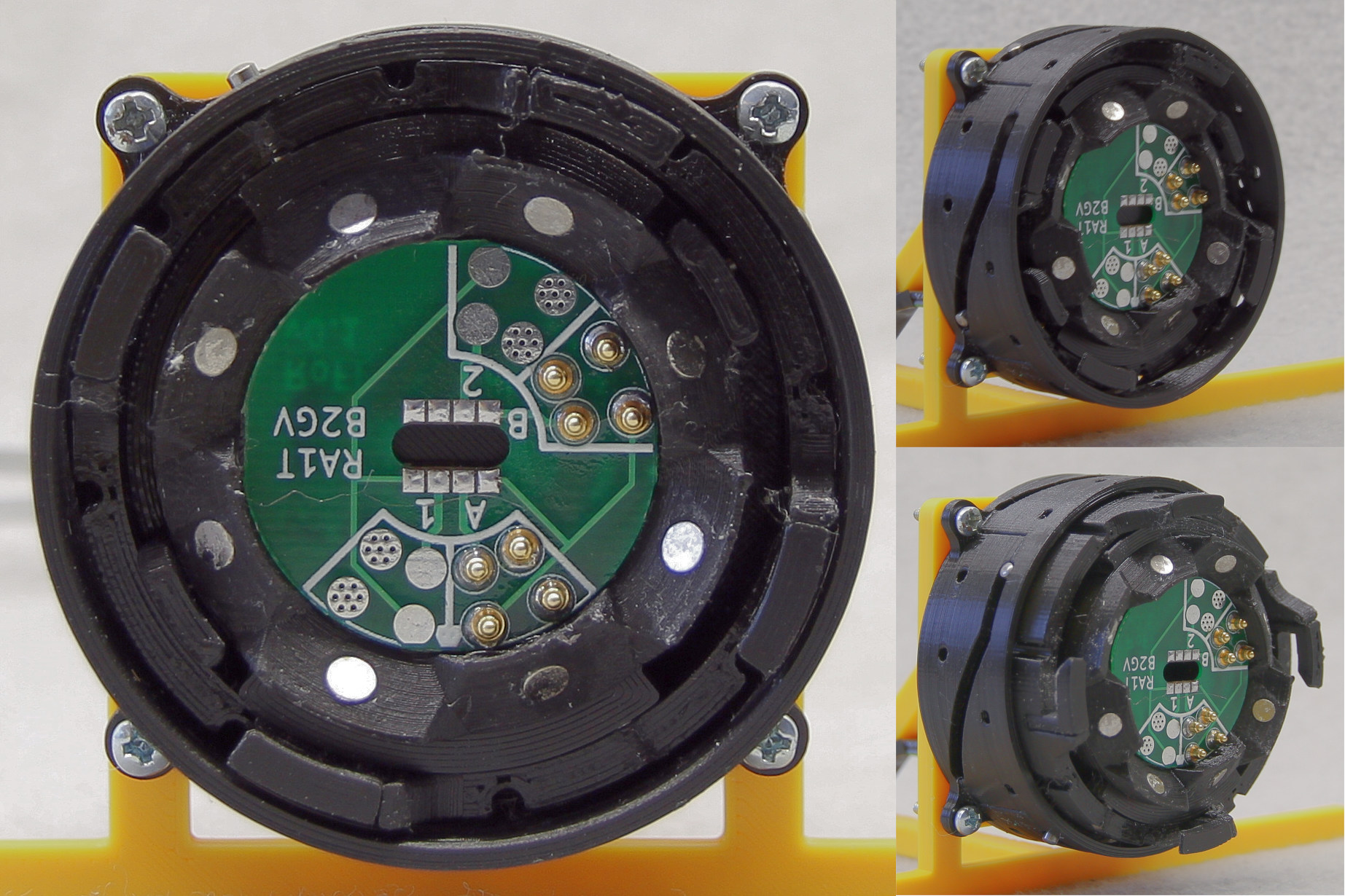
The connectors communicate and share power using a small PCB with spring-loaded pins in the middle of the skirt. The pin layout is as follows:

The layout ensures connection of all lines in all four orientations and also allows for detection of the mutual orientation of the connectors.
The connectors communicate over UART with 8 bits, no parity and a 1.5 stop bit at 6 Mbaud/s. The words are transmitted in a little-endian byte order. The communication protocol between two connectors is simple as the only allowed operation is to pass one binary blob from one connector to another. The blobs are wrapped in a frame with the following format:

The frame is transmitted to the mating connector over UART. If the mating connector is unable to handle the incoming frame or the frame is corrupted (CRC mismatch), the connector can discard the frame. Bytes of the outcoming frame are required to be sent consequently with no additional delay. There is a silent period of 8 bytes (14 µs) after each frame. The receiver should discard an incomplete frame after the silent period and prepare for a next incoming frame. The hardware can implement baud rate correction algorithms and leverage the constant header 0xAA for this purpose. The content type field identifies the content in payload and allows to transmit various protocols over the connectors, (e.g., IP datagrams, RoFI debug messages, RoFI firmware upgrades etc.). The connector is allowed to treat different content differently (e.g. rearrange them in the send buffer, drop them, etc.).
Connector to Module Interface
The connector provides SPI slave interface on 3.3 V level to control the connector. The chip select pin (CS) also serves as an interrupt to the master – when an interrupt is issued, the pin is pulled low by the slave. Words are transmitted in the little-endian byte order, bytes are sent most significant bit first. The data are read at the rising edge of the clock signal. The connector should support at least 10 MHz clock signal. There can be multiple variants of the connectors (e.g., variants featuring sensors). There is a unique number identifier assigned to each connector variant. So far, we specify only connector variant 1 with no sensors, further referenced as a base connector. The following text describes revision 1 of the communication protocol. Future revisions might be released, but they must be backward-compatible. The communication on the bus is performed in transactions – each transaction starts by master pulling CS low and end by releasing CS back to high. Incomplete transactions must have no observable effect. Each transaction follows the format:

Both, command data and the connector response, require no padding. The commands 0–127 are reserved for the base connector, and all connector types are required to support them. The commands 128–255 are connector type specific. The basic commands are:
Version Command
Version command (0) has no command data. The response is in the format:

Status Command
Status command (1) can be used to query connector status and issue status changing commands like expanding or retracting the connector. We consider following bitfields for this command:
- P (position, 1-bit)
- 1: expanded connector
- 0: retracted connector,
- I (internal, 1-bit)
- 1: the INT line is connected
- 0: the line is disconnected,
- E (external, 1-bit)
- 1: the EXT line is connected
- 0: the line is disconnected,
- C (connected, 1-bit)
- 1: the connector is connected (the sense pin is active)
- 0: the connector is disconnected and
- O (mutual orientation, 2-bit)
- 0: north,
- 1: east,
- 3: south,
- 4: west.
The command data consist of two parts: a status bitmask and a write mask. By setting a corresponding bit in the write mask, we can change the state of the corresponding feature of the connector to the state specified by the status bitmask. E.g., by setting bit I to 1 and setting corresponding bit in the write mask, the INT line will be connected. Zeroes in the write bitmask are left unchanged. The format of the command data is:

The connector response follows a similar format as the command. The connector returns the status before performing the command. It also sends the count of blobs waiting in the buffer for transmission, the count of blobs not retrieved by the master and the voltage and the current on the power lines. The voltage is in 8.8 fixed-point number in volts, the current is in 8.8 fixed-point number in Amperes. The format is following:

Interrupt Command
Interrupt command (2) can be used to query an interrupt reason and to enable and disable interrupts. There are following interrupts:
- C – a connect or a disconnect event occurred (the sense pin change) and
- I – a new binary blob received.
The data command is a bitmask with enabled interrupts:

The response follows the same format:

Bits set to 1 signal interrupt reason. After the response is sent, all interrupt reasons are cleared. Therefore, the mask returns all interrupts reasons from the last query.
Send Blob
Send blob (3) is used to send a binary blob. There are no command data. The extended data are formatted as follows:

The size of a blob should be less than 1500 bytes (to be compatible with Ethernet). However, the connector might supporter larger blobs.
Receive Blob
Receive blob (4) is used to obtain a received blob from the mating connector. The oldest received blob is sent. The command has no data. The response follows the format:

If there are no pending blobs, a blob of zero length is returned.
Source Codes
All sources for the RoFICoM ara available at the Git repository of the project. The repository contains:
- mechanical drawings in Fusion 360
- PCBs and schematics in KiCAD
- source code for the microcontrollers
Building Your Own RoFICoM
RoFICoM is open-hardware, and therefore, if you own a 3D printer, you can build it yourself. It takes roughly 5 hours of a print time and 30 minutes of assembly time to get a single unit.
Required Tools
- Philips screwdriver
- M2 tap
- 2 mm drill
- optionally: 1000 grid sand-paper glued on a flat surface
- optionally: plier might come handy
Bill of Materials
There are several non-printed components. All of them all commonly available in a hardware store.
- N20 200:1 DC Geared Motor rated at 6V (can be sourced in your local robot store, Pololu, or cheap alternatives are available at Aliexpress/eBay)
- 2mm DIN6325 M6 hardened steel pins (2x 5 mm, 2x 6 mm, 6x 10 mm, 2x 12 mm)
- M2 screw with countersink head (3x 12 mm, 5x 8mm)
- 4x M2 plastic spacer
- 8x 3x1mm neodymium magnets
Printing the Components
You can download the archive with already exported STL models of bodies of individual
components. We tested the models with Slic3r and Prusa i3 Mk3. We used the
default 0.1 mm settings. The support material was disabled except for
body-body.stl.
Tips for slicing & printing:
- as most of the models are relatively narrow rings, the print goes faster if you increase number of perimeters.
- it makes sense to use the 0.1mm layer height only for the body, pinion and shaft. The other components are fine with much coarser settings.
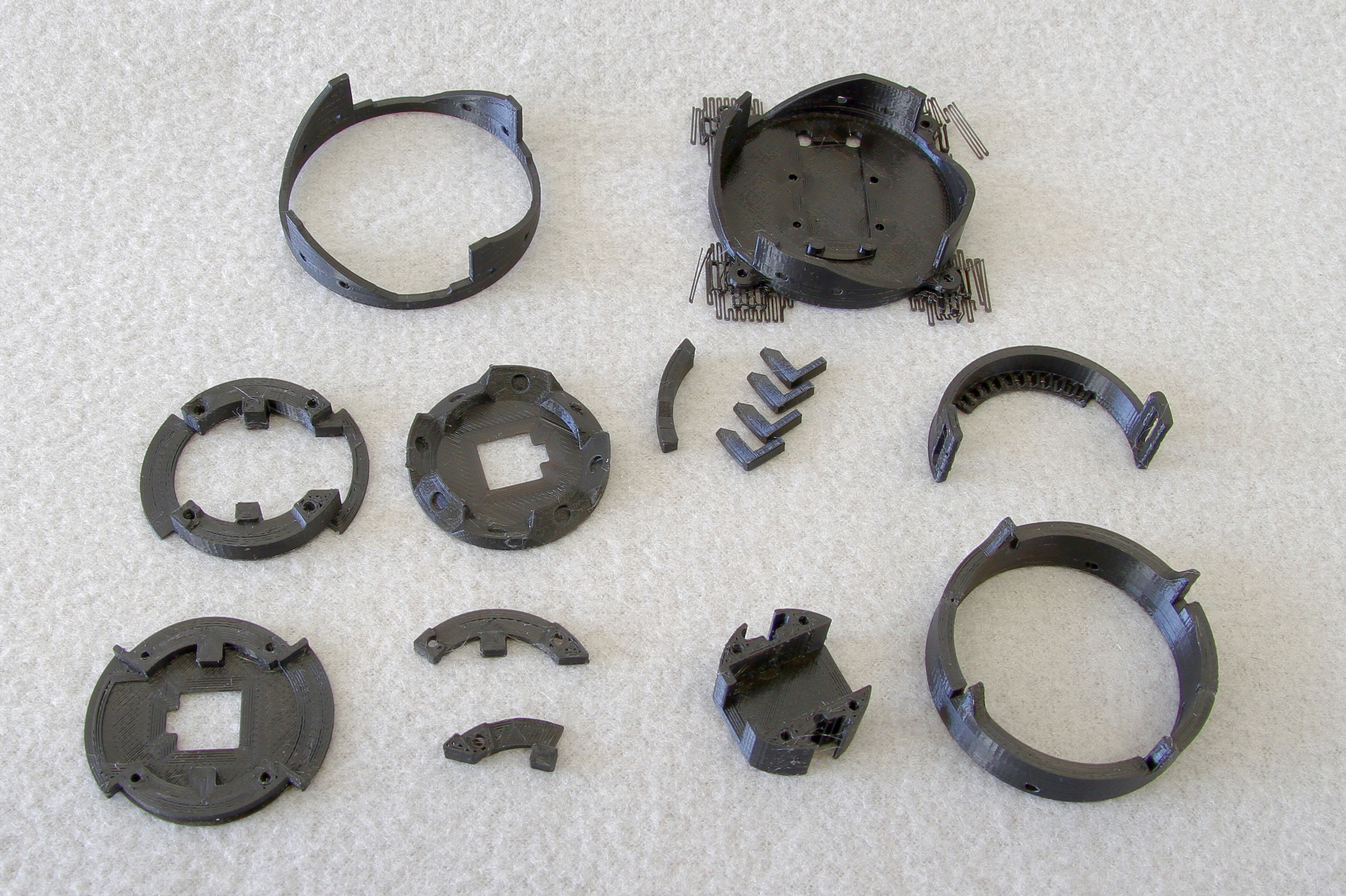
The components you print should look like this:
Step-by-step Guide
Clip Assembly
The clip consists of the following bodies:
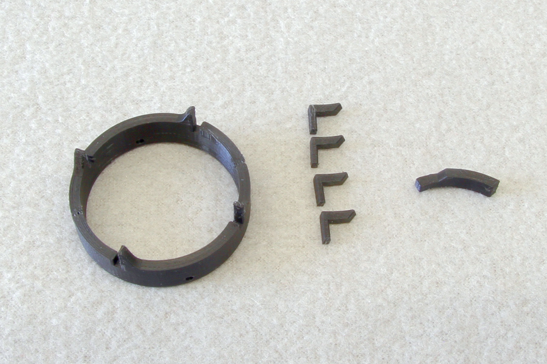
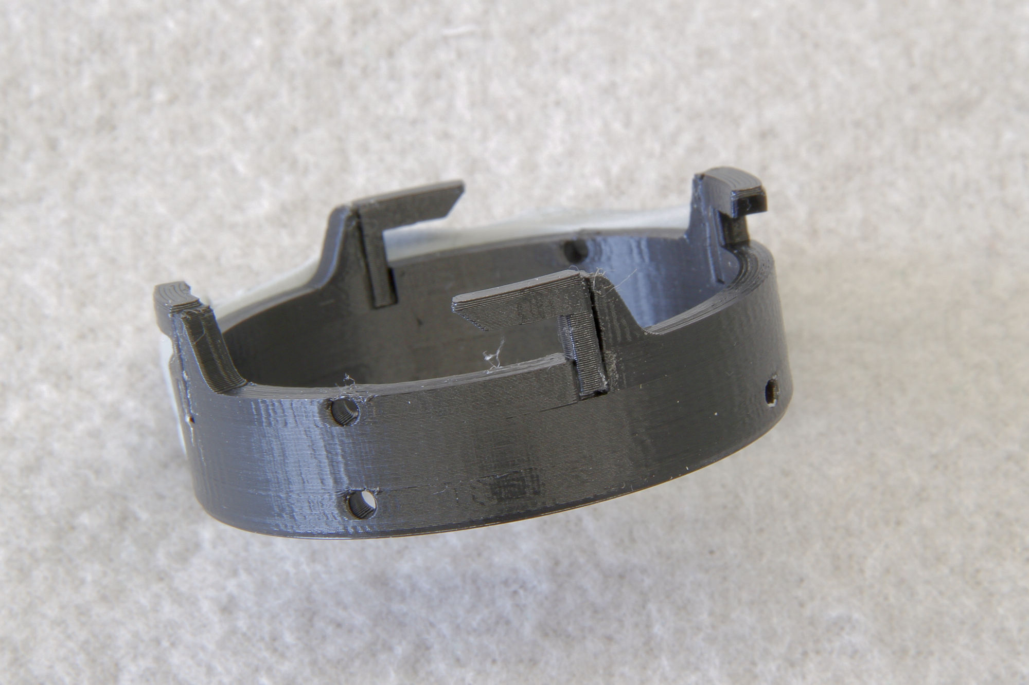
First, glue the hooks into the body using a cyanoacrylate glue. Use a template
(hook_guide.stl) to correctly align the hooks.
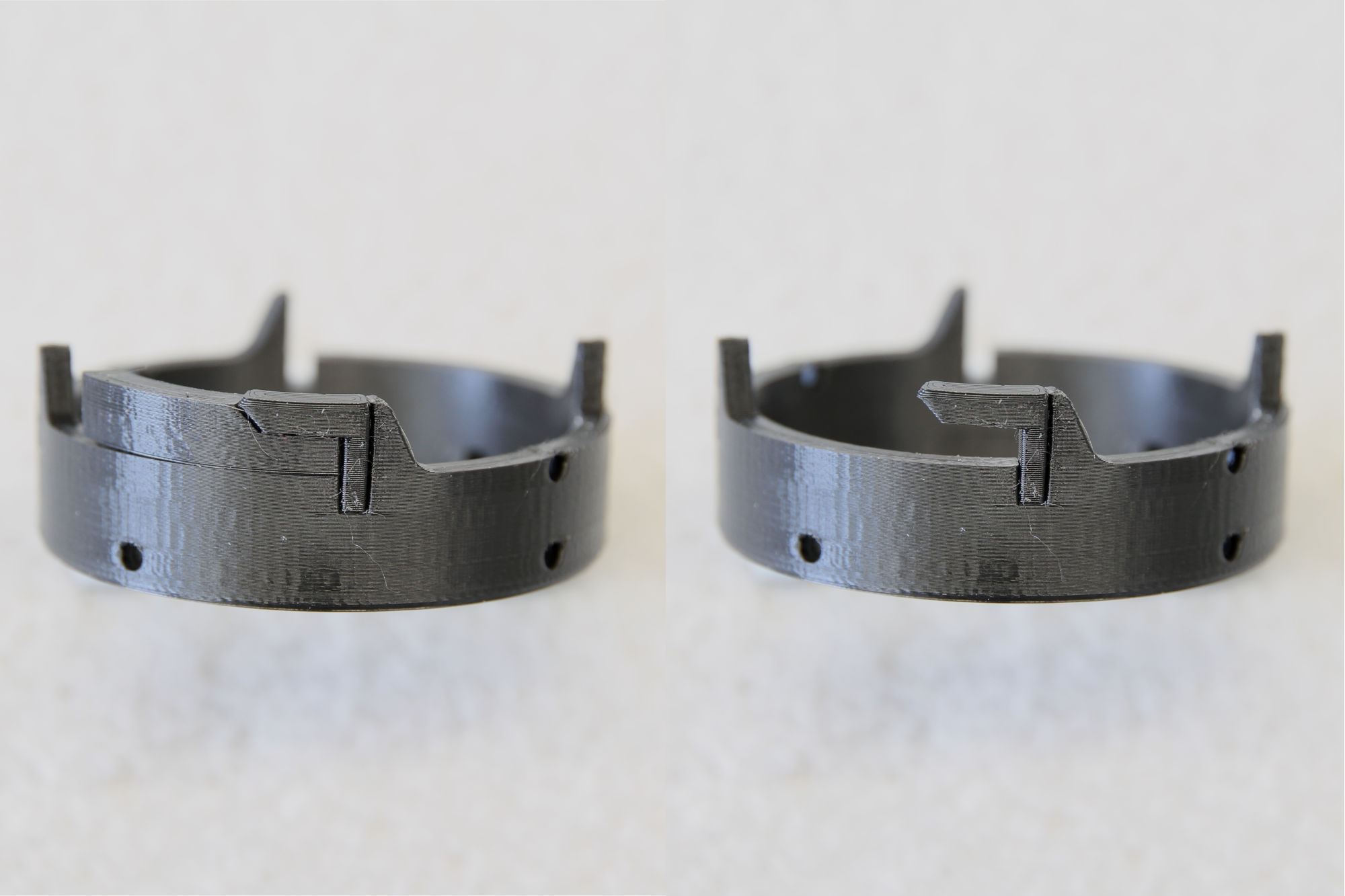
Then, debur the holes on the perimeter using 2mm drill. The clip is completed.
Body Assembly
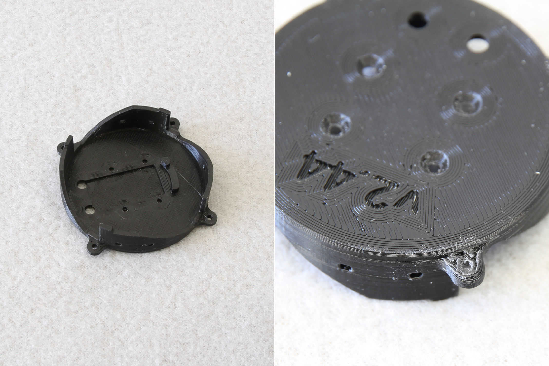
First, remove the support material out of body-body.stl and if necessary,
debur the bottom sides of the mounting holes.
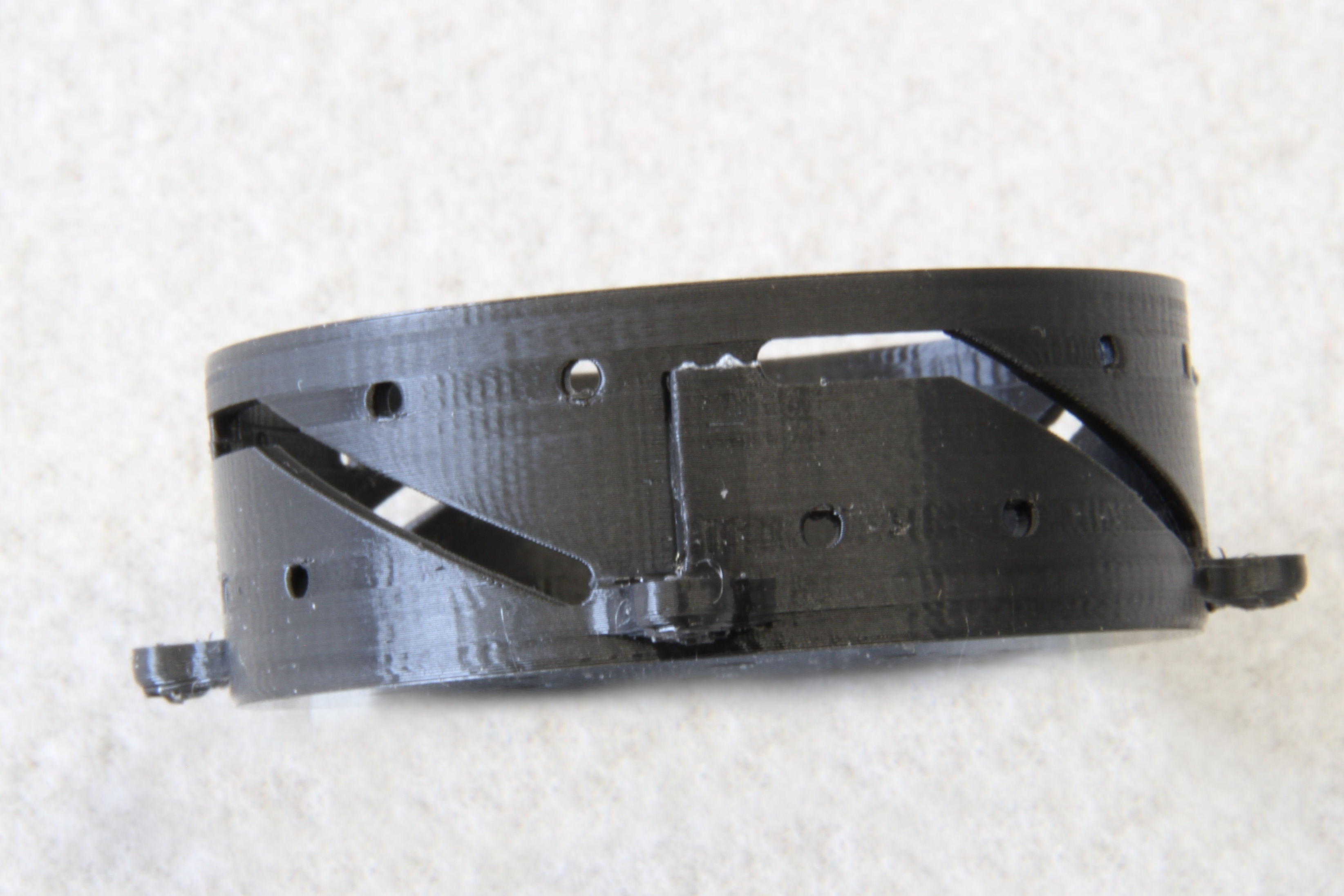
Then glue body-head.stl on top of body-body.stl. Make sure, the pins can
slide smoothly in the slots.
Skirt Assembly
Prepare the bodies for the skirt:
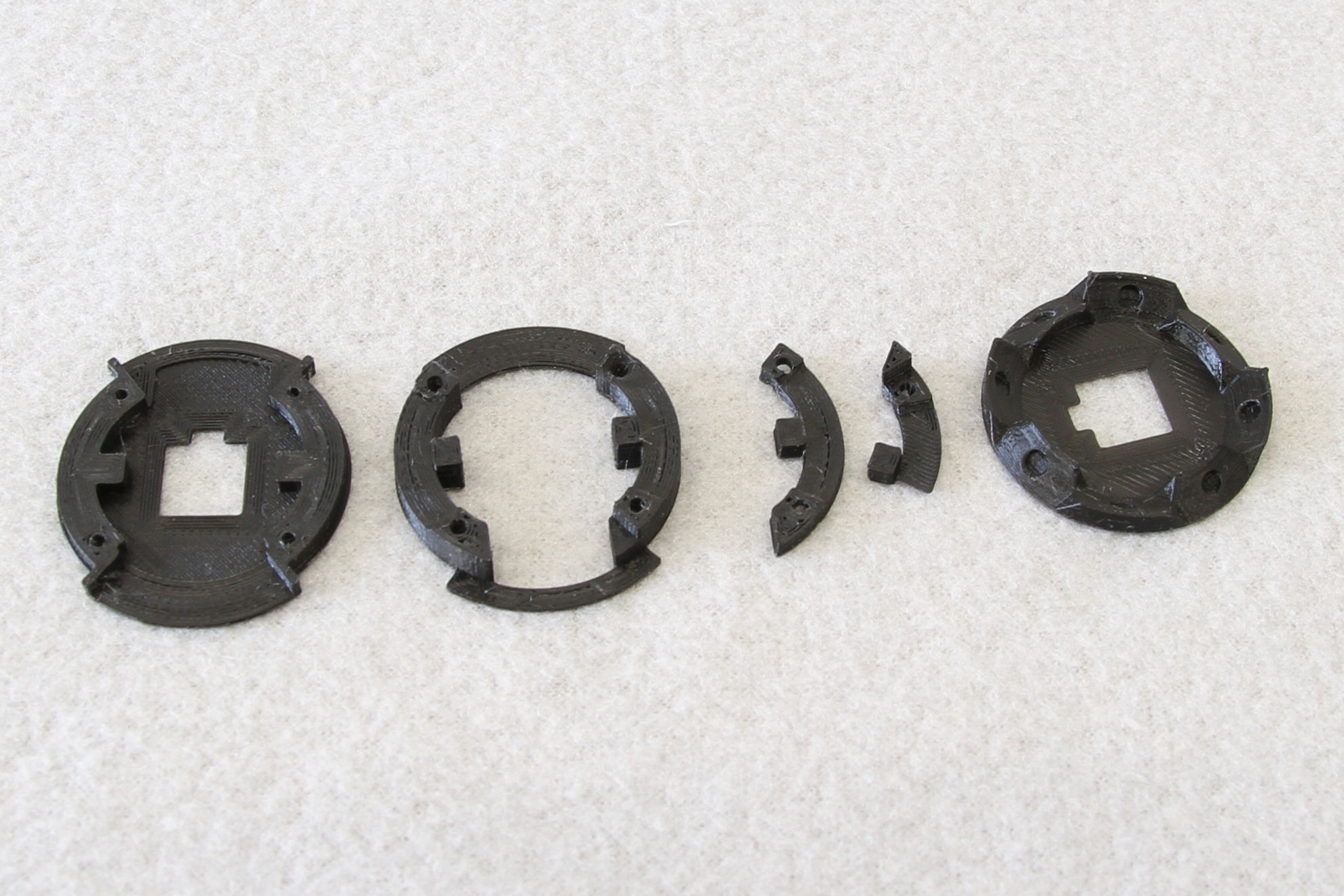
Optionally, if your 3D printer does not produce quality top surfaces, you can use sand paper glued on a flat surface to slightly debur the flat surfaces of the components. It will make the assembly easier a more precise:
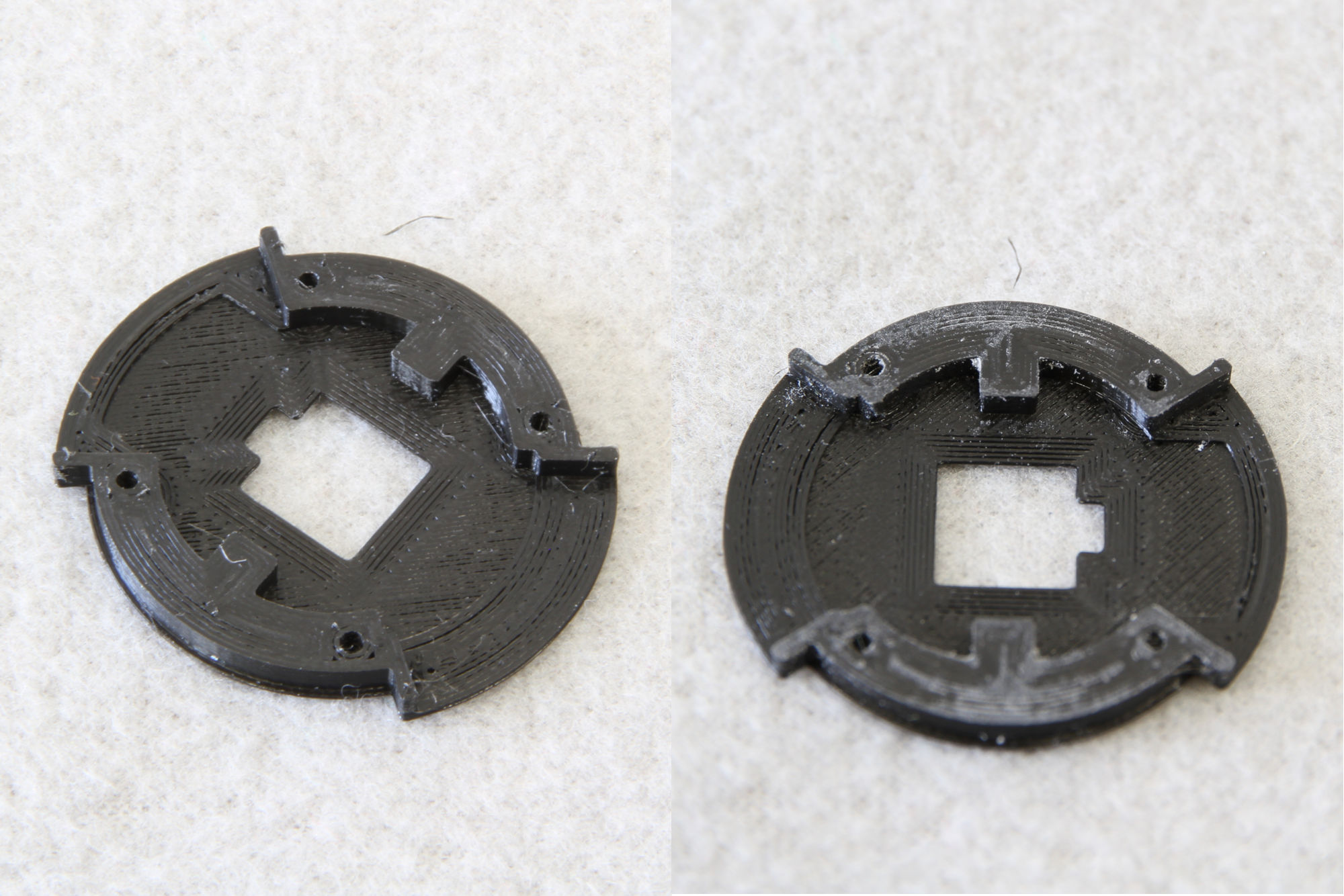
Then tap an M2 thread in the 4 holes in skirt-neck.stl. Also, if the holes
printed on other bodies are not perfect, feel free to debur them using a drill.
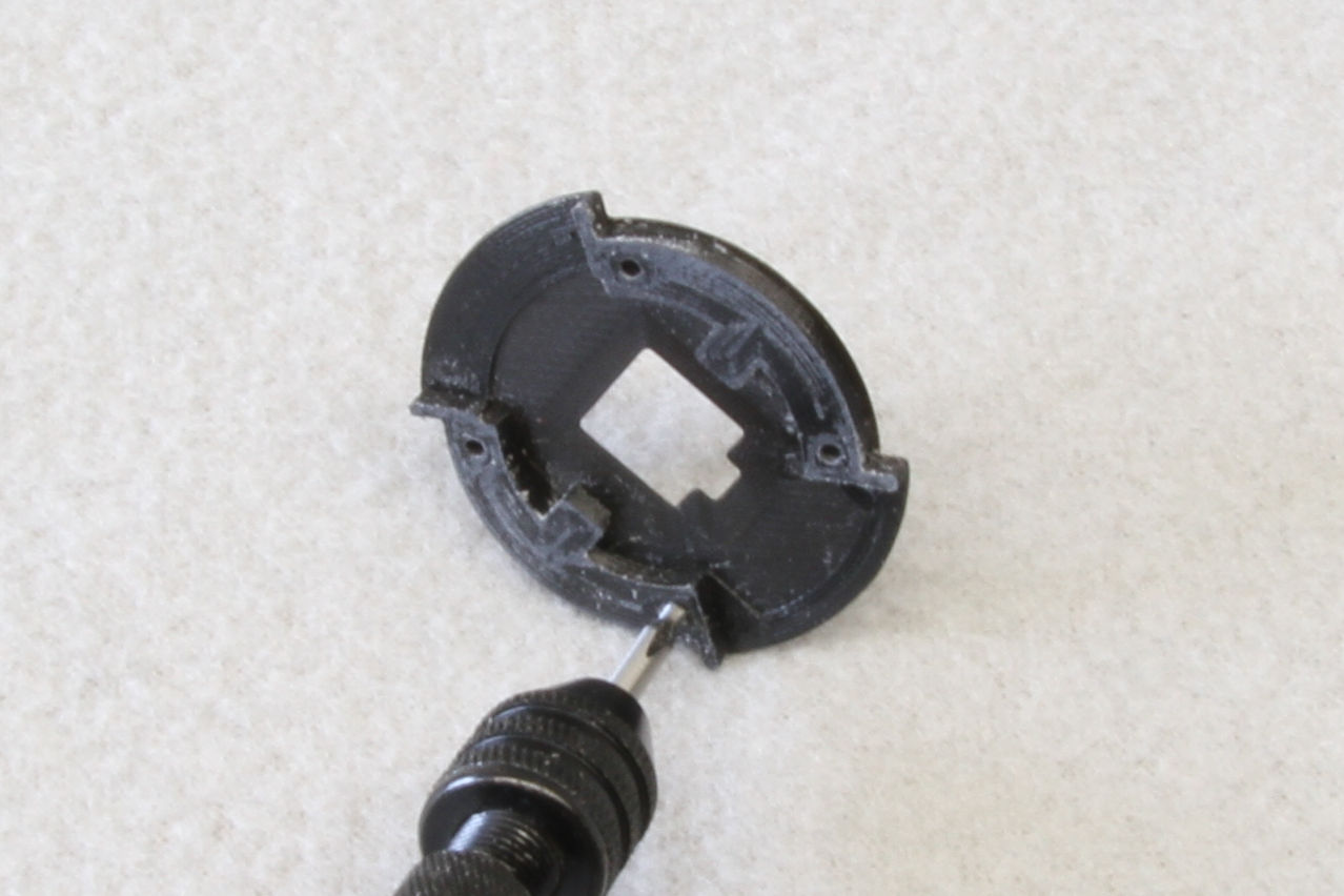
Then use 3x 12mm and an 8mm screw to screw skirt-neck.stl, skirt-middle.stl
and both skirt_{}.stl foots together.
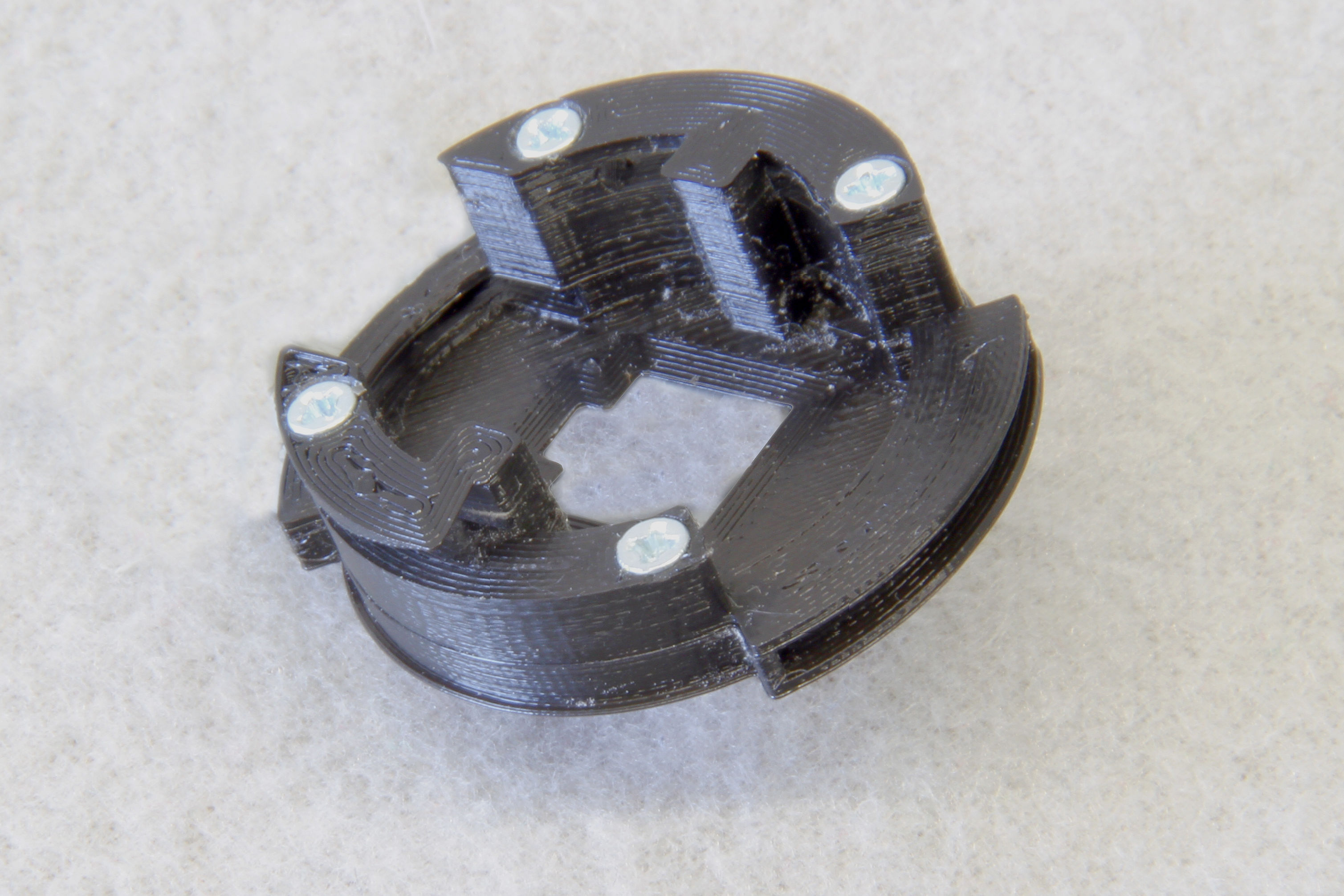
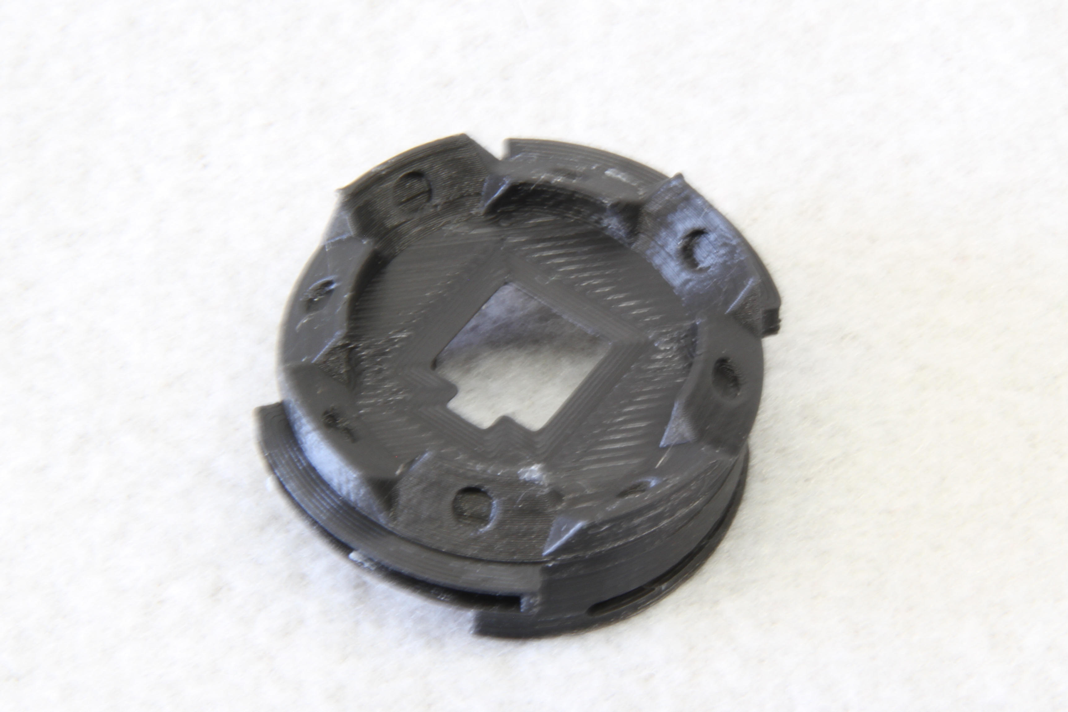
Then glue skirt-crown.stl on top the assembly. Use the screw ends and the
internal cutout to align it properly (please excuse blurred photo of this step)
Motor Clamp Assembly
Even the motor clamp consists of a single body, it is necessary to insert pins with length 10mm serving as a guide rail into the component as shown below. The pins should snap in and hold by friction, there is no need for gluing them.
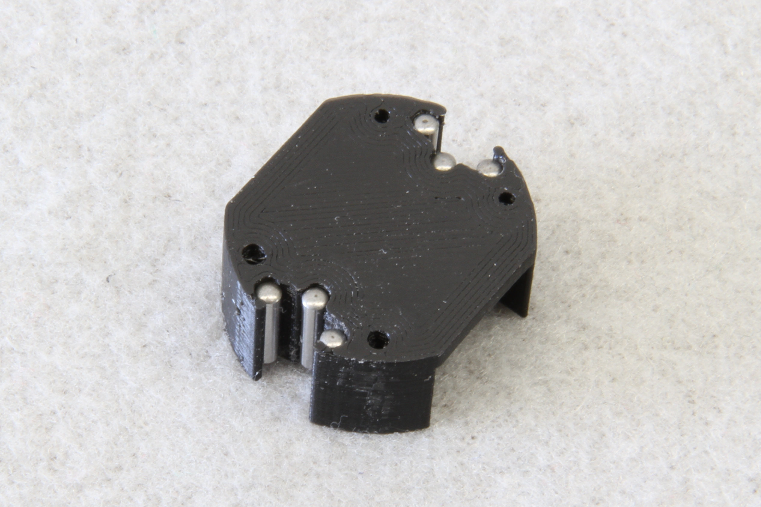
Last, tap the 4 holes with M2 thread.
Final Assembly
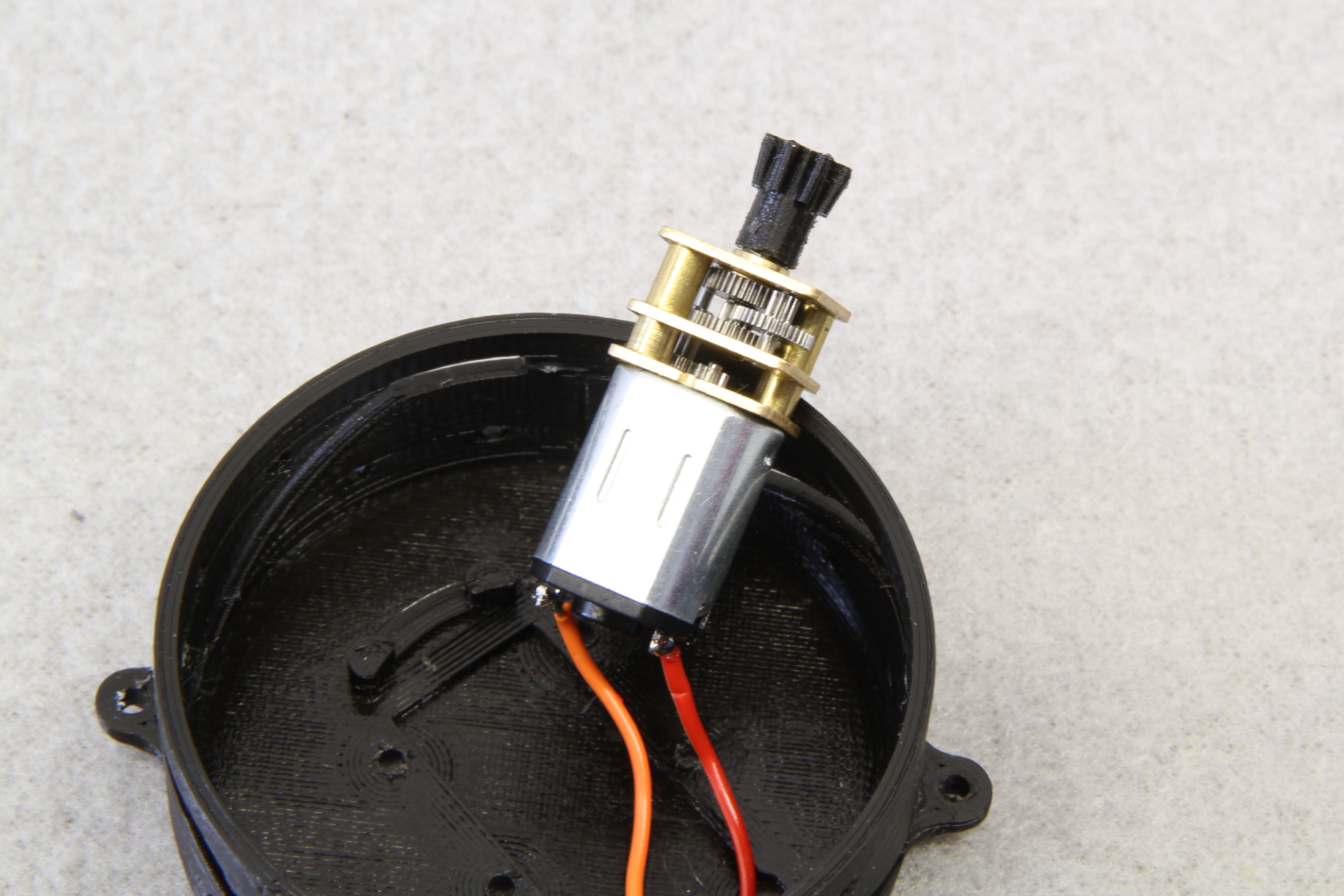
Put the pinion.stl on the motor shaft, put two wires through the holes in the
body and solder them to the motor:
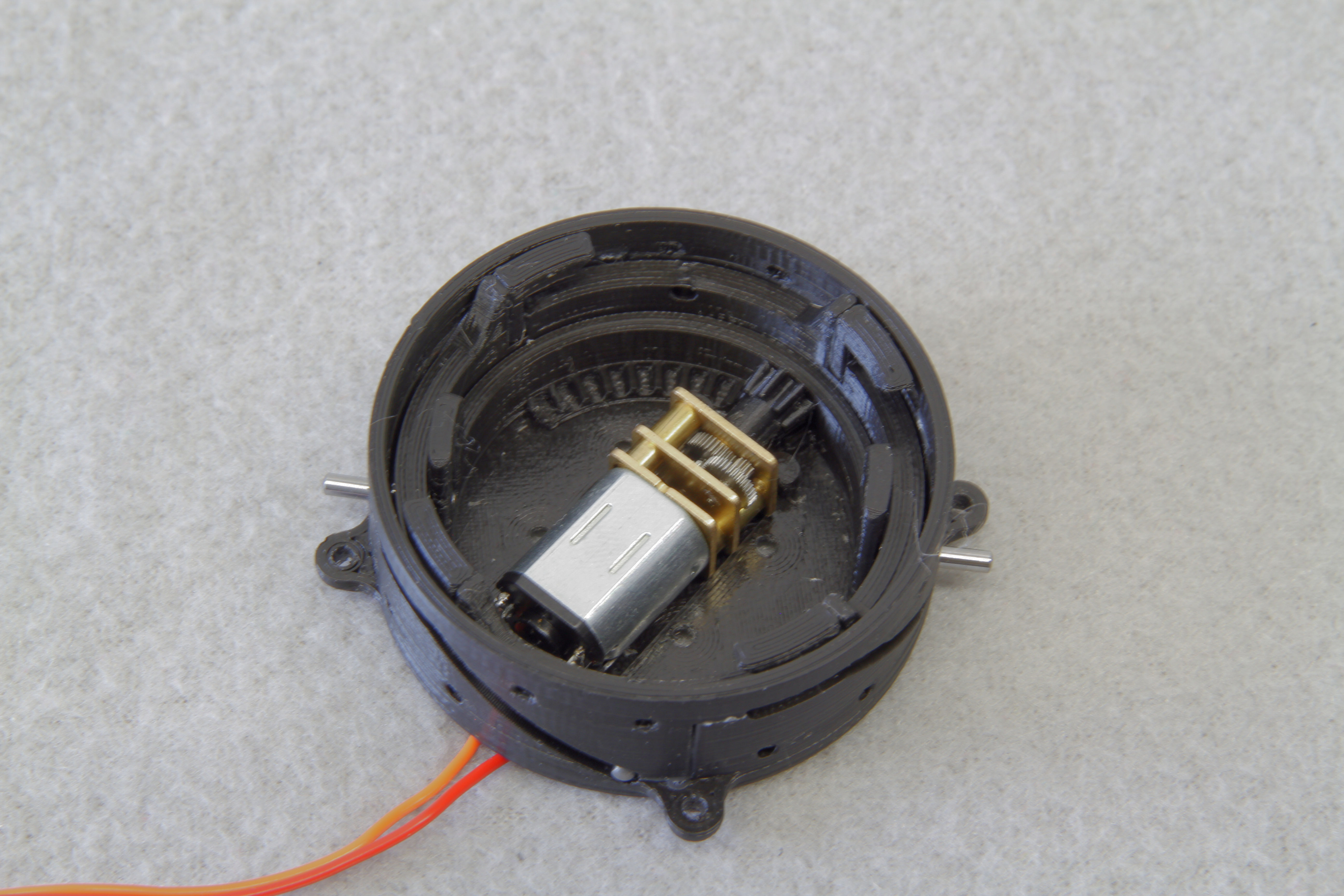
Then, install clip and shaft as shown below and secure it by 2 12mm pins as shown below. There should be spacers on the pins between the body and the clip. Do not put the pins all the way through (yet).
Then install the motor clamp and screw it with 4 8mm screws.
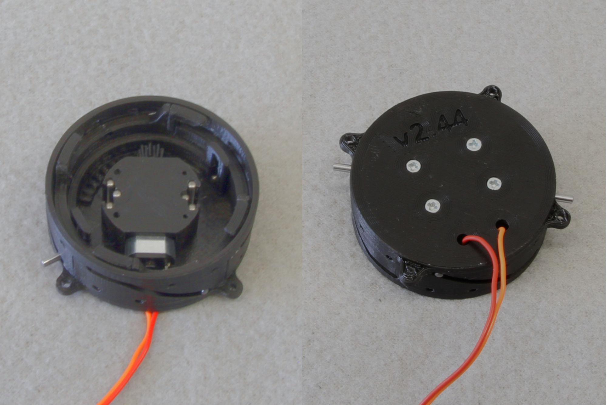
Then put the skirt in the assembly and secure it in the position by pushing the installed pins all the way through. Then install 2 5mm pins in the slots in the body and 2 6mm pins in the holes in the clamp.
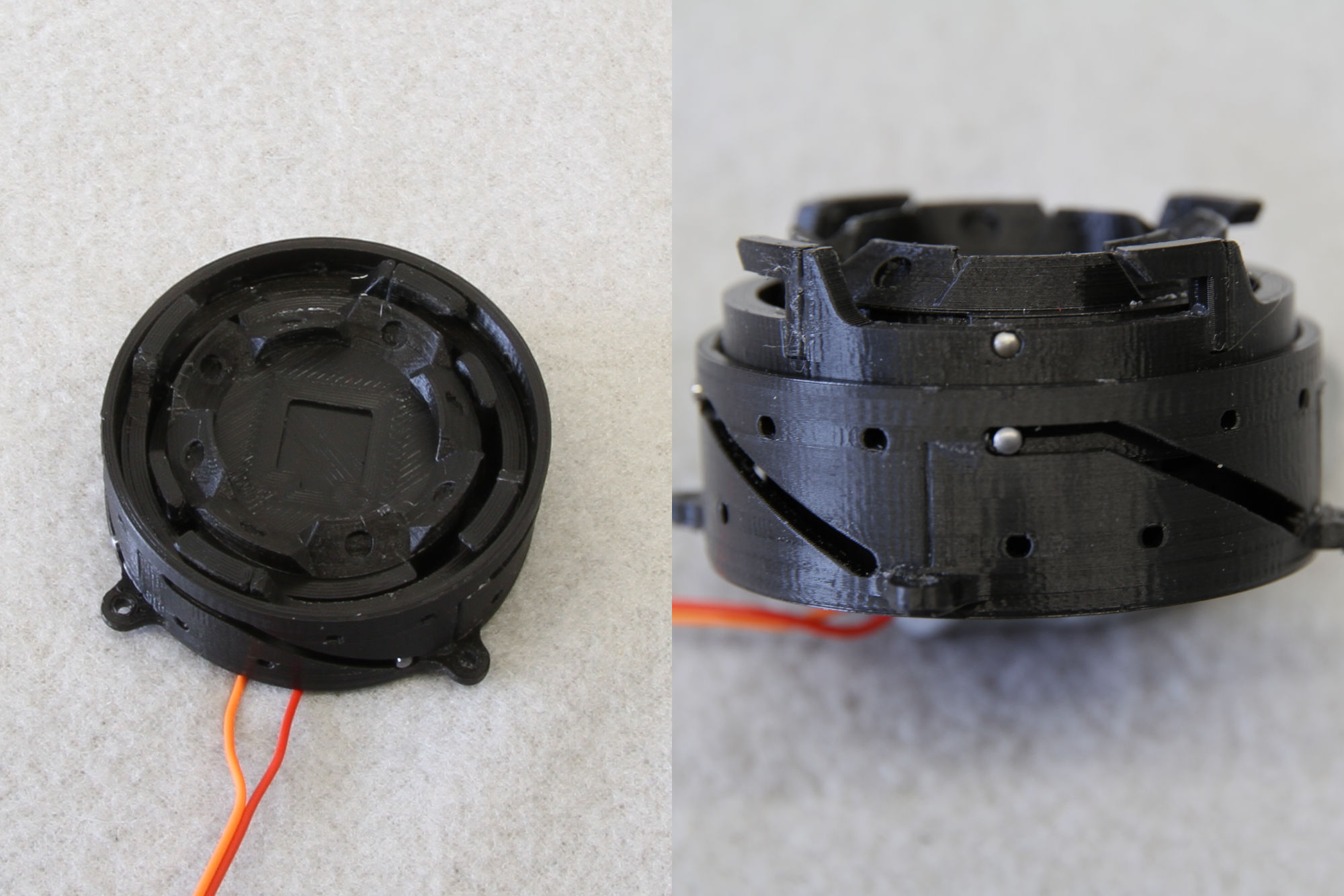
This makes the basic hardware finished. Last, you should glue the magnets in the skirt such that the magnets facing out of the skirt have their south north on top, the magnets facing into the skirt have their south side on top. See below:
