While reconfiguring modular robots, it is not always crucial to get a robot with a specific configuration, but only with a specific trait or ability. For example, we might want to reconfigure a robot into the shape of a snake, so it can cross a gap, or into a spider-like configuration so it can move quickly over difficult terrain. Then it does not matter what ID each module has, whether it is connected to the rest using a connector on one side or the other, but only the overall shape of the robot.
Some solutions include enumerating all possible configurations which share the same shape, or defining a configuration which does not assign concrete modules to positions the robot occupies, but only describes its shape (such as a voxel grid-like or a graph-like configuration). However, these approaches are platform or implementation dependent.
In the following text, we introduce a method to compare the shapes of different robots in general. It takes into consideration the geometrical properties of shapes of modules, and works for any platform of modular robots, provided we define a proper decomposition for each of the used module types.
Meaning of shape
Intuitively, the shape of an object is defined by the outline of its surface. We do not consider factors such as colour, texture, weight, position, size, or rotation, but only the outward appearance of the object. This intuition is captured in the following definition of a shape:
Shape is all the geometrical information that remains when location, scale and rotational effects are filtered out from an object.
This definition works well: by scaling, translating, or rotating an object, its shape does not change. The only point of contention is reflection: the right hand is a reflection of the left hand, but some might consider them to have different shapes. In the context of reconfiguration, it might be useful to look at both possibilities.
To work with shapes of objects algorithmically, we must first define how to represent an object and its shape.
Object representation
To represent the shape of an object, we can select some points on the object’s surface. These points are called landmark points, or landmarks for short.
Landmarks usually correspond to features recognizable on all objects of the same type, so they can be selected consistently and automatically. Additional landmark points can be added artificially to distinguish objects with different shapes, but similar “natural” landmarks. Below is an example of landmark points of a human hand.
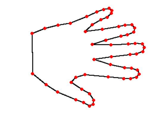
We will refer to the function converting an object to a set of landmarks as decomposition.
RoFIBot landmarks
For the universal module, we have selected six landmarks, each in the center of one of the RoFIComs. Below is an illustration of how a universal module is decomposed:
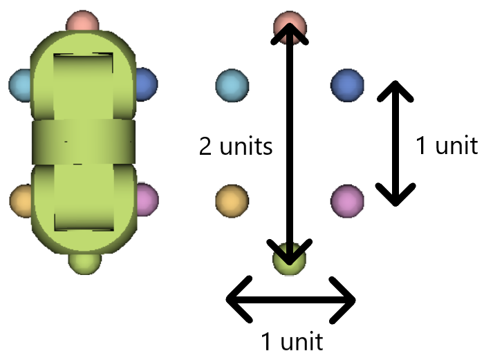
These points were chosen to completely define the module’s shape: rotation of any of the module’s joints by less than 180° will affect the distance between at least some of the landmarks, therefore changing its shape. This is handy, because then a rotation of a joint can be considered as a step in the reconfiguration of different shapes.
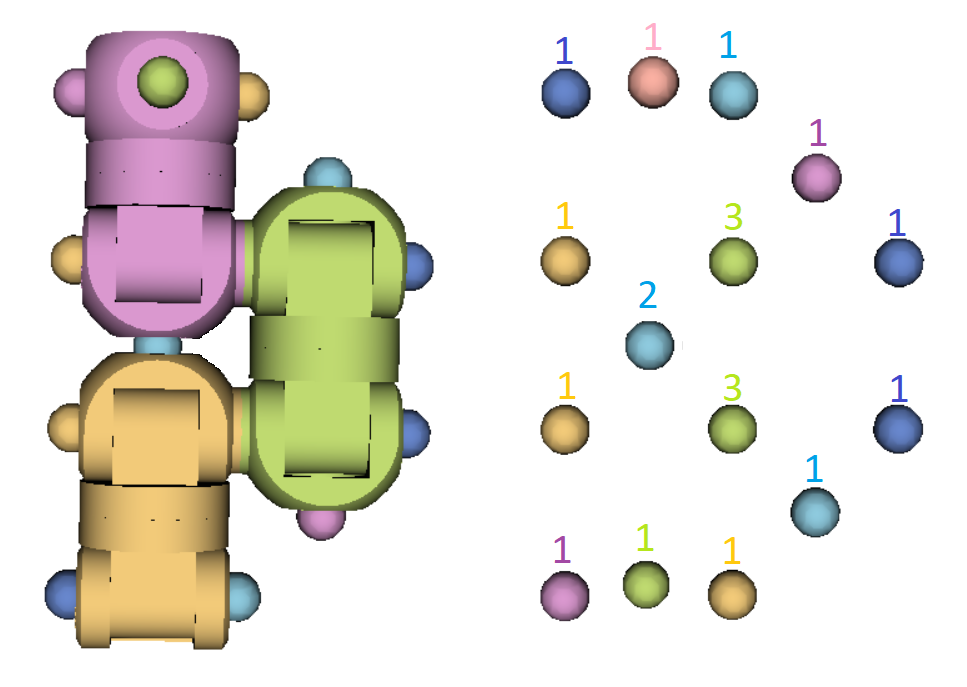
To decompose the whole RoFIBot, we decompose the universal modules, and add a point for every connection of two RoFIComs. This is because we want to consider a dis/connection as a step in the reconfiguration state space. If we did not add any points, a dis/connection would not change the shape of the RoFIBot, leaving us in the same state.
Below is an example of a RoFIBot decomposition. Number next to a point is the multiplicity of the point: two unconnected but adjacent RoFIComs define two points, but connected RoFIComs form three:
Comparing RoFIBot shapes
To decide whether two RoFIBots have the same shape, we decompose them into two sets of landmarks A and B using the described decomposition. Afterwards, we attempt to find a linear transformation consisting of a scaling, translation, and a rotation (and possibly also a reflection) for each of the sets A and B, so that they describe the same set of points. If we succeed, the shape of the RoFIBots is equal, since such transformations do not change the shape defined by the points.
Next we take a look at how we can find and apply the individual parts of the required transformations.
Scale
Although scaling is required to compare shapes in general, we avoid the need to rescale the decomposed points by applying the same decomposition to all RoFIBots. In case two decomposed RoFIBots have an equal shape, the distance between the corresponding points is then equal.
Translation
To filter out the translation factor from landmarks, we can simply shift them so that their centroid is in the origin, which can be done by subtracting the coordinates of the centroid (the “average” point) from each of the landmark points.
Rotation
After both of our sets of points A and B have been centered to the origin, all that remains is to rotate them so they map onto one another. We attempt to solve this by using variance of the points as a reference point. Variance is a property of data that represents how much the data differs from its average; for points, variance of a coordinate describes how much these points are spread out in the dimension defined by the coordinate. If two sets of landmarks define the same shape, the spread of the points is similar as well. Therefore, we find the directions with greatest variance, and rotate both sets so these directions align.
This is exactly what Principal Component Analysis (PCA) does. It can be described as a rotation (and possibly also a reflection) of a given set of points, after which the first coordinate describes the greatest variance. The second coordinate then describes the second greatest variance, and so on. Below is an example of a set of 2D points, and arrows which describe the dimensions of the greatest (direction X) and second greatest (direction Y) variance. Unit vectors representing these directions are called principal components. Because we want to use each component as a coordinate axis, they must be orthogonal to each other.
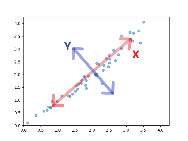
This is almost what we require, but there are two problems. First is that changing the sign of the principal component is arbitrary - changing it does not change its size, variance or orthogonality to other components. The second problem arises when two or more of the found components have the same variance: then the order of the components is not well defined, and, as we will discuss later on, the components themselves are not uniquely defined. This happens when the set of points define some symmetrical shape, such as a circle, or a square. Below is an example of two different RoFIBot configurations which share the same shape, but for which the calculated PCA transformations differ (we would need to change the sign of the Y and Z coordinates for the points to align):
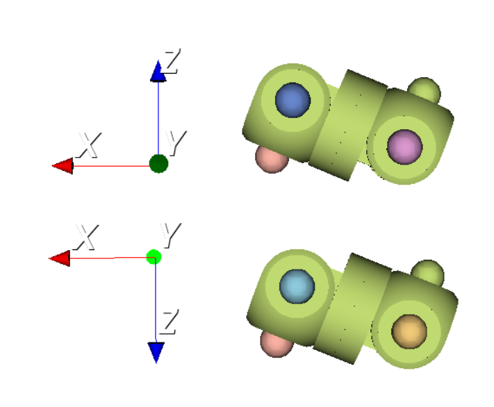
Therefore we cannot rely on the PCA transformations to align the points perfectly by themselves. But the orthogonality of the principal components gives us an advantage we can use: after applying a PCA transformation to A and B, we only need to try changing the signs of components, and changing the order of components with equal variance; if after any combination of negating and permuting axes of A we gain a set of points equal to B, the shape defined by these two sets is similar. This gives us a total of 48 possible combinations to try in the worst case (all three found components have equal variance): there are six ways to order the components, and each can be either negated or not.
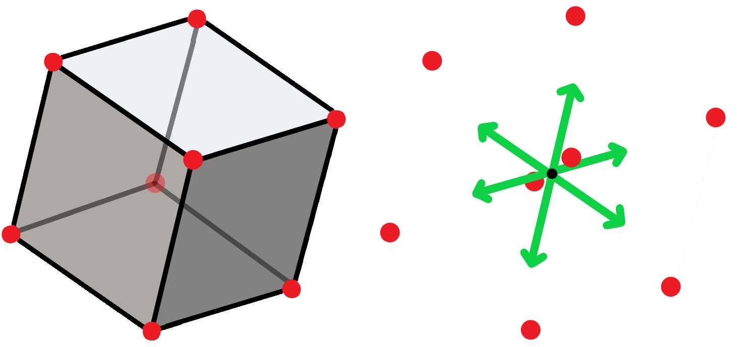
Below is an example of such a case; there are 6 vectors with equal greatest variance, and therefore 48 possible transformations a PCA algorithm could produce, depending on the implementation (and possibly floating point error):
However, in the case of equal variance of two components, there is another problem: there are linear combinations of these components which are also principal components, but are not simply their negations. Below is an example of two possible pairs of principal components found for a similar shape, but which we are not able to align using the approach described above:
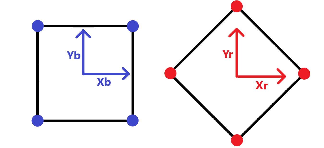
We omit solving this problem, because the introduced method has proven successful in shape recognition of RoFIBots (most likely because the amount of symmetrical RoFIBots is very low when considering robots consisting of more than one module), and we believe it can be used with other platforms of modular robots with similarly consistent module decomposition.
Reflection
A reflection can in some cases change the shape of an object; below is an example of two RoFIBots which are reflections of one another, but we cannot rotate one in space to gain the other without changing the parameters of their joints.
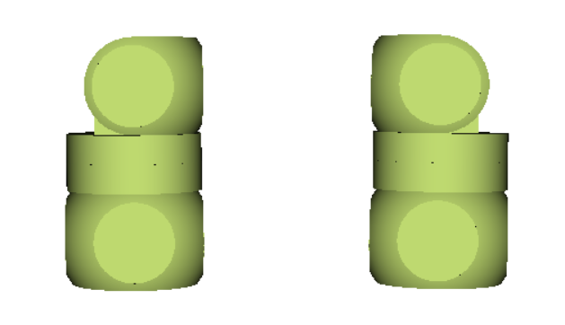
If we want to think of these as different shapes, then the amount of PCA rotations to consider is reduced to 24 at most, which are those that have determinant equal to 1 (a reflection has a determinant of -1). This means besides permuting axes, we only allow changing signs of either zero or two axes at once (changing the signs of one or all three axes at once results in a reflection).
